Homemade Joystick - Part 2
The next update on the joystick I started a few weeks ago.
The horizontal axis was way too loose, which meant the gears had too much play and started skipping when you moved the stick quickly. So I had to re-make the end support. Now it is ridiculously stiff instead. Hey ho.
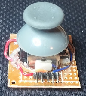
Another thing I've made is a module for an analogue hat to go on top. I stripped out the components from a knock-off XBox 360 controller I got ages ago on ebay and attached one of the joysticks to a piece of matrix-board. I'm still not entirely sure how I want it wired up to the Arduino, so I bought some right-angle header pins that I can attach jumper leads to later on.
The joystick had four mounting tabs, which poke through the board so they can be bent and soldered to provide a strong physical bond between the component and the board. I had to enlarge the holes with a twist-drill, but they lined up pretty well so it wasn't too troublesome.
The microswitch for the press-button was through-mount, so that was pretty easy to wire up, if a little fiddly to line up with the holes in the board. The wire from that could go straight from the header pin to the microswitch pin.
However, the potentiometers were surface mount. First, I tried to fill the hole with solder to make a connection through to the other side of the board. That failed.
So then I decided to solder the wires directly on to the potentiometer pins, poke them through the board and solder-bridge them to the header pins. This came really close to working, but my ineptitude at making solder-bridges kept pushing the wires and header pins back out of the holes in the board.
I ended up stripping a lot of insulation off the wires so when I poked them through the board, I could bend the metal over and solder it directly to the header pin. This worked pretty well.
Next time, I might poke the wires through the board from the under-side to solder on to the potentiometer pins. That way I can route them more easily across the under-side and solder them directly to the header pins.
For now though, the multimeter says it all works - I just have to figure out the other components and the physical structure of the stick itself. No biggie!


Comments
Post a Comment