Posts

Showing posts with the label Crazy Projects

DIY Luggable Pentium

Image
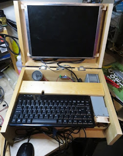
 Ages ago, I bought a Socket 5 Pentium via Ebay.  I had mounted it in a DIY wooden case just so I could use it, but it was always a bit of a pain to fish out a 4:3 monitor, PS/2 keyboard and mouse and connect it all up. So for a long, long while I have had the idea of making it into a 'luggable' machine.  Finally today, I have made it a reality.   I had an ancient monitor kicking around that ran off a 12V input and I had tested powering it from an ATX PSU.  I dismantled it with the idea of using it for video and audio.  Unfortunately while removing it from its case, I managed to damage the cable connection for the speakers, so then I had to dig out an old speaker from a box of scrap. Annoyingly, this motherboard did not have an amplified output - only a line out.  So I bought a cheap amplifier module that works off 5V so I could power it off the PSU's 5V line.  This has led to an annoying amount of noise in the output - I suspect from the PSU. The...

Picante: Audio

My plan was always to do a SID-style synthesizer so I could make C64-style sounds on the picante. I've managed to make a thing! This is a software synth running on a RaspberryPi Pico attached to an Adafruit UDA1334 I2S module (recorded through the mic jack on my PC). Getting the UDA1334 working The official Adafruit guide was useful, but not perfect as it didn't cover the Pi Pico.  The micropython examples on how to play a tone and how to play a wav from an sd card were really  useful though. First, I got the play tone working, then I adapted the sd card (non-blocking) interrupt to play a continuous tone (which was just beautiful and didn't make my ears bleed at all). Starting on the Synth I then had to do a LOT of thinking about how I could make this synth fast enough and low-RAM enough for a Pi Pico.  After trying out a few combinations of parameters, I settled on a sampling rate of 16kHz and 16 bits per sample.  I wanted the synth to work on different wavef...

Picante: Transparency and Text

Picante: Basic Graphics Features Complete! The fundamental graphics feature set is there:  clearing the screen drawing 32x32 bitmaps with optional transparent colour index drawing coloured text from bitmap font All features are accessible via python script and clip against the screen edge. It's not yet built to be robust - I was having too much fun to bother writing exhaustive error checking. Whilst the basic design is meant to be fairly speedy without eating too much RAM, there's plenty more that can still be done to optimise it. Blitting: The tiles are processed from a single bitmap, but blitted individually (no fast tilemap feature yet).  It runs at about 15fps, all off a single core.    Text: The text is processed from a png into a 1bpp binary format for the picante engine to load.  This runs at about ~20fps. It's designed to be able to handle any font up to 8x16px, but I've only tested it with the 3x5 tom-thumb font so far.  The small screen really ne...

Picante: Render Buffer Go Bye-Bye

What's gone wrong My initial approach to rendering in a timely manner involved native/C code to 'blit' bitmaps to an 8bpp render buffer.  Every frame, that render buffer is expanded into 16bpp stripes for transfer to the display.  At about 18-19fps, this was pretty tidy. The next step I wanted to take was to render tilemaps to the background, so I found a tileset online and converted into bytes() objects in a .py file for import...and promptly ran out of RAM. The New Proposed Approach So then I started looking at a 4bpp (16 colour) render buffer with colour palette, and I didn't like the amount of pixel operations involved in drawing to it, let alone expanding it out to the stripe for display. So my intention now is to store a list of render commands for each stripe of the display.  These commands could be partial 'blits' of a bitmap, or straight colour-fill, or whatever else.  The key thing is that they are only actually executed once all render commands have b...

Picante: a Pi Pico-based handheld project

Image
In The Beginning... I'd been experimenting with SPI displays on the Micro:bit before now and was lamenting how little RAM they have. So when I read about the Pi Pico 's whopping great 264KB of RAM I immediately wanted to make a DOS-a-like handheld game platform.  It easily has enough RAM for a full 320x240x8bpp frame buffer and at 133MHz it's about the same speed as an original-series Pentium.  Plus, it's dual core! All those figures made me think it would be an absolute doddle to make a DOS-a-like. ...but then I started to think about how it would actually be used.  Sure, I could make it so that C programmers could make games for it, but that might just end up with curiosity value. But what if I could make it so that the students I teach could program games in Python?  That way it would have loads of inspiration power whilst also having high educational value! With the magic mix of both idea and plausible use case, I set about making a prototype. The Hardwa...

Adventures in C64 repair

My C64 is still banjaxed, but now in a way that makes me feel it's closer to being fixed. I had thought it was just a dead PSU, so I ordered a new one.  When it arrived, I plugged it in and.....the same problems happened.  So that's the first potential fault ruled out. So I ordered a C64 dead test cartridge .  When this arrived, I plugged it in and powered on...and it gave me all sorts of crap on the display.  Still recognisable characters and border, but utter random garbage.  There was some screen flashing, which is the way the cart indicates dead-ram chips, but it couldn't decide which one - every time I switched the machine on it gave a different number of flashes. The internet had already suggested that garbage text meant a duff multiplexer, and with the cart encountering seemingly random errors across multiple chips, I decided to order a couple of spare multiplexers (there are two in the C64). So today I cautiously desoldered the U13 multiplexer and solde...

Steering Wheel Finished!

Image
Here it is, immortalised with my atrocious photography skills! It's made mostly out of some old tongue-and-groove flooring samples, with some 4mm and 6mm ply in places.  What with the heavy-duty bearings and being screwed together, it's actually a really robust little thing! I decided to have a composite axle so I could fit the button wires down the centre. So I cut two long, thin beams of ply so they could fit through the very centre of the bearings.  Then I cut small sections out of the edges so that when pushed away from each other, they would lock into the bearings (i.e. not slide through them).  The other blocks you can see are holding the two long pieces apart so they can't fall out. I swapped out the middle block with a spring mechanism.  I cut two bits of ply that I could slide onto the beams from opposite sides.  Then I inserted a section of bamboo skewer between those bits to hook the springs onto.  As you can see, I used screws to secure the othe...

NAS 'Case'

Image
I dun maed a frame for my home NAS machine.  It's been sitting as an untidy pile of connected components for just too long, so I finally did something about it. And here it is in-situ under the stairs: It's made from plywood off-cuts - the back from an old cupboard and the sides and drive supports from when I put boards up in the loft. I tried holding the PSU in with battens, but the glue wouldn't hold and they split when I tried using screws.  So instead I sank dowels into the plywood.  You can see four in the photo (two on the back board and two on the side), but there's another two on the back board holding the PSU's weight from underneath.  Rather improbably, it's actually quite a strong fit and the only way to get the PSU out is to slide it upwards. The bar across the front hooks onto two dowels (one from each side-board) so I can easily get at the drives to replace any failures.  It's got corrugated card on it to dampen vibrations and provide some grip...

Trellis DONE!

 OMFG, I have been intending to make this bloody loganberry trellis for SO LONG!  And I've finally done it! Somehow, this weekend, I managed to get my sorry ass out to the workshop and cut, assemble and paint the damned thing.  It's just two A-frames joined by a couple of cross beams - nothing fancy.  It is about 7ft to the top of the A-frames, and it supports the loganberry canes at about 6ft (so I can put nets over them to stop the damned pigeons getting at them). I'm still not sure why my brain was so strongly rejecting the task of building them.  It might've been the amount of wood piled up in the workshop, making it feel unsafe to even go in there.  The new school year starting was probably also a big factor.  Anyway, it's done now, and it feels great to not have it hanging over me any more. Now I can start planning my next task...a better USB joystick with SPRINGS.

Joystick Realisations

Image
Yesterday I had extreme difficulty in doing air-to-air refueling in DCS World. The obvious reason for that would be that it is an extremely difficult thing to do and I am just not good enough yet. Not being happy admitting my own lack of ability, I decided to blame my homemade joystick. To be fair, my joystick was built by a numpty (me), so there could easily have been something screwy with it. When researching more expensive potentiometers, I discovered that 'linear' potentiometers do not necessarily give a linear response to changes in angle.  It depends on potentiometer model, temperature, and all sorts of other things. Seeing as the potentiometers I used were the cheapest I could possibly find, their quality is questionable at best.  So I figured I'd have to measure the response curve, then hard-code a calibration fudge. I was genuinely surprised with the results: There is a beautiful linear section for part of the response, but the bit from 55-75 degrees is just shock...

Wall-Mounted PC: Progress!

Image
The actual physical progress I have made is a monitor wall-mount made from battening and MDF. See the monitor hanging magically with no visible support! I made a frame for the back of the monitor from 3 pieces of 6mm MDF: I knew the bolts I had could only go in so far before I hit resistance (presumably from the internal components).  As far in as I was confident tightening them would leave ~9mm gap.  So I figured 12mm of MDF would be fine. WRONG.  It turns out you have far less wiggle-room on these things than I thought. So I had to countersink them through the outer layer.  That gave me the fear though because the outer layer would be the only thing really holding the monitor onto the wall bracket.  So I decided to glue the layers together as well as having the bolts.  It took a couple of tries to get the countersinking to the right depth, but it got there! And before I did anything else, I tested that the panel from the wall-brac...

Homemade Joystick - Part 3

Image
Final mammoth post about an epic journey... TLDR: I dun maed a joystick out of wood and Stuff. The Abridged Backstory: I've been planning this for literally years .  The tools and materials available to me have expanded over that time.  My original plan was to make it out of cardboard using a Stanley knife and PVA.  Nobody was convinced that was going to work. This one is mostly built out of hobbyist plywood and dowels using a scrollsaw, power drill, Stanley knife and scalpel. The Base Frame: I have talked about the base frame in a previous post . A brief side note: My 3D printer is a relatively cheap setup from ALDI .  Software set up was a breeze on a Windows laptop.  I chose to print patterns from SD card rather than laptop (laptop hibernate aborted models halfway through).  I needed to cleanup prints with a scalpel afterwards, but has worked fine so far with no obvious signs of wear. How I'd do it differently in future: I'd try...

Homemade Joystick - Part 2

Image
The next update on the joystick I started a few weeks ago . The horizontal axis was way too loose, which meant the gears had too much play and started skipping when you moved the stick quickly.  So I had to re-make the end support.  Now it is ridiculously stiff instead.  Hey ho. Another thing I've made is a module for an analogue hat to go on top.  I stripped out the components from a knock-off XBox 360 controller I got ages ago on ebay and attached one of the joysticks to a piece of matrix-board.  I'm still not entirely sure how I want it wired up to the Arduino, so I bought some right-angle header pins that I can attach jumper leads to later on. The joystick had four mounting tabs, which poke through the board so they can be bent and soldered to provide a strong physical bond between the component and the board.  I had to enlarge the holes with a twist-drill, but they lined up pretty well so it wasn't too troublesome. The microswitch for th...

PC Shelf 'Case'

Image
TLDR: I made a shelf for my desk and mounted my PC components on it.  Lookit! Having changed my PC desk a while ago, I've been growing gradually more annoyed at my tattered cardboard PC case sitting as an eye-sore in plain view of the whole living room.  The hard drives were hanging loose and the cooler radiator was balanced precariously on top. After much thought, I decided to add a shelf to my PC desk.  That way the PC could be off the floor, and the components could show through the glass desk-top.  Fixing a shelf to the metal box-section desk frame would not be easy, but I decided on drilling holes through the frame and bolting the shelf to it. Making the MDF shelf (with some battening to keep it rigid) was fairly easy.  Drilling the holes in the frame was a pain in the backside.  I should really invest in some proper drill bits for metal.  Eventually, after realising my M4 bolts were too short to fit through the wooden battens, I dug out ...

PC Controller Supports

Image
TLDR: I made a desk-like thing which attaches to the arms of my computer chair (see pictures below). Recently I changed my PC desk to take up less space in my living room.  The new desk is an IKEA metal/glass laptop desk.  Unfortunately it was about an inch too long to sit in the gap between my fire hearth, so I had to prop up the other side on bits of wood.  This made the desk too high for comfortable use of my cardboard steering wheel. So I designed and built a work-surface which attaches to my PC chair. The first step was to make some struts which sandwich the chair's arm rests.  They are secured with carriage bolts and wing-nuts/washers from Wilko. Then come the blocks with dowels which are screwed to the struts, and the work-surface which sits on the dowels. The surface is reversible and asymmetrical so my keyboard/mouse can sit close to me.. ...but my steering wheel can sit further away. As shoddy as it might look, I'm quite proud ...

GRG16 - Now with keyboard input!

The original goal was to make a Mega-drive-like virtual games console which wouldn't have a keyboard.  After some thought, I realised that keyboard input might help me with both the teaching/learning goals (by giving scope for a wider variety of activities) and the development (by giving me easily testable incremental steps towards the final program). So now I have a keyboard device which populates two memory locations: one for the currently-depressed key, and a second for the current modifier state (CTRL, SHIFT, ALT). Plus, after much painful debugging, I have a program written for the VM in assembler which reads the key state and displays typed characters to the screen. This highlighted the need for development/debugging tools for the virtual console itself, and I am seriously daunted by the prospect of having to develop them. Also, I no longer like the BusController being in its own separate thread.  I've already had problems with the compiler optimising out re...

GRG16 Update

Image
Back in March, I posted an update talking about a bunch of stuff I would do. Nearly 5 months later, those things are pretty much done (with a couple of tweaks), and here is the jaw-dropping screenshot!!!! What do you mean, your jaw hasn't dropped? O_o Tbh, I can understand you being underwhelmed.  It is a singularly unimpressive screenshot, and the blank column on the right shows it doesn't even work properly. BUT! What the GRG-16 program is actually doing is loading and running a binary ROM file which contains the definition of the screen (set of character codes) AND assembler code to draw that definition to the screen. So behind the scenes, there are many moving parts.  There is an assembler which can take a text file and put together a binary ROM with instructions and data. Then there is the GRG-16 program itself, which has a CPU, ROM device, graphics device and a 'BusController' to copy data between them. At the minute, this is based on an SDL ...

Sculpting: Control Panel

Image
I have been playing around for literally years trying to sculpt and cast miniatures / scenery bits.  I have been plagued by (amongst other things) silicone leaks, air bubbles and sheer clumsiness.  Today I have won a hard-fought victory against air bubbles! When putting resin into a silicone mold, air bubbles get trapped in all the hard-to-reach places.  I tried a few things to get rid of them: Pouring a little resin in, then 'rolling' it around the mold by tipping it all different directions.  It spilt some resin, and took up some of its valuable pot-life.  Results: poor (although it might work for larger models). Adding flow-channels to model/mold.  This involved cutting away channels of the mold, or adding sprue-like protrusions to the model itself when making the mold.  It was very hit-and-miss, with some larger models coming out great some of the time.  Air would still end up getting trapped though, and the channels meant extra resin ...

GRG16: Update

Progress on the GRG16! I decided the next project waypoint for me was going to be an emulator which loads a boot/BIOS rom which will display a 'No cart inserted' message on screen.  This seemed like a good target because it would mean integrating some kind of programming, defining graphics data and enough of the emulator machine itself to display it. So far, progress has been slow but steady.  I have implemented a rudimentary assembler in Python which can also include raw hex.  The current version can parse/assemble asm code and also extract pixels and/or palettes from images (using the Pillow Python library).  I'm sure there are plenty of bugs still to find in it, but the file it produces passes the quick-scan-in-a-hex-editor test. I've also made some progress on the emulator side.  In addition to the VPD I worked on previously, the CPU is pretty much implemented, and I've just implemented a BusController to move data between boot/BIOS rom, cartridge, RAM...

Cardboard Mock-up of USB Joystick

Image
For years now (literally years ), I have been playing around with the idea of making a USB joystick.  You may have seen my previous experiment in building a throttle control . I wanted to use a similar idea to the throttle, taking the angular motion of the handle and magnify it when applying it to the potentiometer.  e.g. move the handle through 45 degrees and the potentiometer gets moved through 90 degrees. I also wanted it anchored at the rear, so I can build a mount to attach it to my computer chair. In the video you can see a cardboard mock-up I made today.  I'm amazed it worked at all, but it even provides a solid foundation for designing the proper plywood one. The process of making a cardboard mock-up was really useful.  There were three fatal flaws in my sketch design which I would not have found out until I tried to make it: Pushing the joystick left/right when it was already pulled full back makes it catch on the rear support. The internal ...